How to Build an MSF Radio Time Receiver
How to build an MSF radio time receiver
Introduction
Requiring no testing, aligning or specific electronic experience it is easy to construct an MSF receiver using modules from Galleon Systems. All of our modules include the necessary support documentation and are tested before shipping.
While not as accurate, and without many of the functions of a dedicated radio referenced NTP time server, it is possible to build your own MSF radio referenced atomic clock receiver for relatively little cost.
Requirements
To construct your own MSF atomic clock receiver there are really only 6 main components:
Modules
These 3 modules are available from Galleon Systems - click on the links for further details.
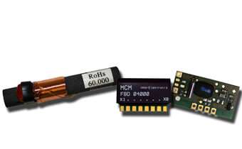
- An em2s receiver module: When combined with a ferrite antenna, the receiver module acts as a complete unit for the reception of time code signals.
- MSF Ferrite Antenna: The MSF signal is broadcast at 60 kHz and a suitable ferrite antenna pre-aligned and LC tuned is best.
- Microcontroller decoder: required to decode the signal into a standard data format.
Power Supply
2 main options for powering the circuit:
- 3 volt DC supply
- 3 volt battery/battery pack
Note: The MCM-RS232 module must only be powered from 3 volts - anything higher will result in damage to the module.
Decoupling Capacitors
Decoupling capacitors are used to reduce noise to the signal being transferred to the receiver. However, only trial and error will determine the strength of the noise as this will be dependent on the environment the receiver is to be used in and the distance from the transmitter.
RS232 serial interface
An RS232 serial interface is used to connect your MSF atomic clock time receiver to a computer.
Decoupling capacitors and the RS232 serial interface are available form any good electronics specialist
Enclosue / Housing
Because of the compact size of the modules supplied by Galleon Systems any small plastic box will suffice.
Important: use a non-conductive enclosure - metal boxes can cause interference or blocking of the time signal!
Construction
Mounting of the modules can be done either on a small circuit board or the modules can be pinned or glued directly to the enclosure.
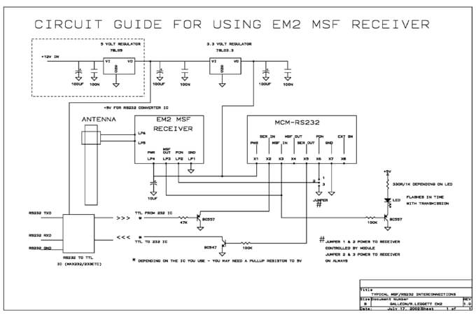
A schematic of the basic wiring of the modules is shown below. Note the optional use of an LED as in indicator that the device is working normally.
As the schematic demonstrates the modules are very simply wired together:
- The antenna is best laid horizontally as it is to be aligned with the direction of the MSF signal (when siting the device it is recommended to use a compass and map to locate the direction of the transmitter in Cumbria - latitude 54° 55' N, and longitude 3° 15' W ).
- The antenna is connected to the EM2 MSF module (LP6, LP5).
- The power supply connects to both the EM2 and the MCM-RS232 module (LP4, X1 3VOLTS, LP1,X7 ground).
- The EM2 and MCM modules are connected via the MSF out (LP3) and PON (LP2) on the EM2, to the MSF in (X3) and PON (X6) on the MCM module.
- The MCM - RS232 connects to a computer via a serial interface and the Serial in and out (X2 and X5)
Note the location of capacitors and resistors to overcome the problems associated with noise. As mentioned earlier some trial and error may be required in this area.
Software
There are several options when it comes to software to control the MSF receiver. Whilst there are multiple types of time synchronisation software available including freeware, Galleon Systems Time Sync version 3.2 is highly recommended. Time Sync has an easy to use interface and can synchronise to not only a radio receiver but also GPS and the Internet. Time Sync v 3.2 is also fully supported with a fully informative manual containing troubleshooting advice and a self explanatory interface. It also has many functions unavailable in smaller shareware synchronisation packages and will run on Linux and all versions of Windows (at least as far back as NT/2000). Galleon's software will automatically detect the device and send the time signal to the ntpd daemon (or service in Windows) which will run in the background. The program will also determine the MSF signal from the decoded pulses.
Troubleshooting and Accuracy
One of the main causes of problems with a simple radio receiver such as this one is noise. Even if the noise is filtered and smoothed out by the use of capacitors it only takes a small amount of noise, particularly when the signal is in a low state, to generate an error. If the daemon or service detects an error whilst trying to decode the time signal it aborts the current process and tries again.
To reduce the interference:
- keep the device away from metal objects
- keep the device away from other electrical equipment
- keep the device's antenna aligned at right angles to the location of the transmitter
The biggest factor in defining accuracy of any radio clock is the distance from the transmitter, its propagation, the processing of the receiver, and the latency of the operating system. Because of all these factors a delay of up to 20 milliseconds can be expected and while this can be calibrated for in Time Sync v 3.2 accuracy up to 20 milliseconds is more than precise for most if not all time synchronisation needs.
Visit our international sites:
Popular Products:
NTP Enterprise Time Server
GPS synchronised NTP Enterprise Time Servers with PPS locking for large networks.
GPS NTP Server
A Network timeserver using the GPS signal to synchronise time across large computer networks.
NTP Network Clock
The perfect partner for any Galleon NTP server or time server. Display consistent and accurate time throughout your organization.
Network Time Server
A complete solution for synchronising the time across any computer network.
Time Server
GPS clock providing time synchronisation for computer systems


