How to Build an MSF Radio Atomic Clock Receiver
For all students, University and College who would like to recieve there MSF modules free please click here
Introduction

Atomic clocks use an atomic resonance frequency standard as their timekeeping element and are by far the most accurate chronometers possible with the latest Strontium based atomic clocks boasting a precision of a less than a second lost in several hundred million years.
The clocks maintain a continuous and stable time scale called International Atomic Time (TAI). However, for civil time, another time scale, Coordinated Universal Time (UTC)which is derived from TAI, but synchronized using leap seconds to UTC, to keep it based on the rotation of the Earth.
UTC is a global timescale that is commonly used to synchronise the clocks on computer networks allowing machines from across the globe to communicate together and conduct time sensitive applications. Unfortunately atomic clocks are highly expensive pieces of equipment and are generally only to be found in high technology physics laboratories or onboard satellites. However, several national physics laboratories broadcast the time told by their atomic clocks via a long wave radio transmission. These signals are commonly picked up and utilized by radio controlled wall and desk clocks and by NTP time servers (Network Time Protocol).
The transmissions from the national standards agencies maintain an accuracy of 10-9 seconds per day (approximately 1 part in 1014). MSF is the signal broadcast by National Physical Laboratory in, Anthorn, Cumbria. Other countries boast their own signals the most common being the DCF77 transmission broadcast from Mainflingen near Frankfurt, Germany and the USA's WWVB signal broadcast from Fort Collins, Colorado.
All these times signals work in a similar way. At the start of each second the strength of the signal is either reduced by between 6 and 10 dB or switched off for a specific amount of time before being restored. The amount of time the signal is reduced is used to indicate a stream of binary numbers with positioning markers. The exact format of the code varies between each signal although they are similar in format.
Dedicated NTP time servers that attach to a computer can utilise this signal to synchronise computer networks to. These dedicated devices are ideal for keeping networks running accurate time and can typically keep a network accurate to within a few milliseconds of UTC time.
While not as accurate, and without many of the functions of a dedicated radio referenced NTP time server, it is, however, possible to build your own MSF radio referenced atomic clock receiver for relatively little cost.
Requirements
A simple MSF receiver can be constructed quite simply requiring no testing, aligning or specific electronic experience. Simple receiver modules can be bought direct from companies such as Galleon or retailers like Maplin. The benefits of using complete solution modules over discrete solutions is that the modules include the necessary support electronics, tuned crystals and are pre-assembled and tested. In constructing a MSF atomic clock receiver there are really only three parts:
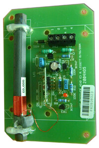
- A receiver module: When combined with a ferrite antenna, the receiver module acts as a complete unit for the reception of time code signals. With an additional level matching circuit, the demodulated output signal can be used to directly drive a decoding circuit. The modules can be adapted to any available transmitter by simply replacing the crystals.
- MSF Antenna: The MSF signal is broadcast at 60 kHz and a suitable ferrite antenna pre-aligned and LC tuned is best.
- Microcontroller decoder: required to decode the signal into a standard data format.
Any lecturer or student interested in acquiring this equipment please contact us on: 0121 608 7230 (UK) or +44 (121) 608 7230 (overseas) and Quote "EMC-FREE". Or by email: enquiries@galleonmail.com
EM2S Receiver Module

The module has a low-power standby mode with maximum 1'A current consumption. In active mode the current consumption is less than 1mA, typically 500'A. The data output is connected internally with an active low open collector NPN transistor. EM2S Receiver Module General Specifications:
- Dimensions: 25mm x 13mm x 12mm approx
- Nominal operating voltage: +3V DC to 12V DC
- Operating voltage range: 2.2V to 15V DC
- Recommended voltage range 3V to 5.25V
- Current consumption at+3V, active: 1mA
- Standby: 1mA
- Output: Open collector NPN transistor, active low
- Maximum sink current: 15mA
- Maximum collector voltage: +5.25V
Ferrite Antenna
This pre-aligned LC tuned ferrite antenna is specifically designed for use with the EM2S Receiver Module. Antenna General Specifications:
- Dimensions: 60mm x 13mm or 100 mm *13 mm
- Nominal operating frequency: 60 kHz or 77.5 KHz depending on model
- Resonant frequency: 60 kHz - 300Hz or 77.5 - 300Hz
- Bandwidth (-3dB) : 700Hz Sensitivity:8-V output voltage with 100'V.m-1 field strength
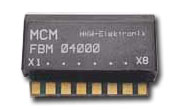
MCM-RS232 Microcontroller Decoder Module

When combined with the EM2 Receiver Module and the Antenna, this module provides time information in standard RS232 data format via a serial interface. External buffering to full RS232 levels is required and can be achieved using a proprietary RS232 level shifter IC. The advantage of the module compared to direct host decoding of the receiver output is the presence of exact decoded time information all of the time and no processing overhead. The module also features a real time clock that recalibrates itself against the Atomic Radio Time Signal when it synchronises with the Atomic Radio Time Signal.
MCM-RS232 General Specifications:
- Dimensions: 22mm x 13mm x 5mm approx
- Nominal operating voltage: +3V DC
- Operating voltage range: +2.4V DC to +3.6V DC
- Current consumption at+3V, active: 1mA - Standby: 50-A
- Inputs: Time code data input (from EM2S), or EM6.
- Serial data input (from host PC via suitable level converter)
- Outputs: Power control output (for EM2S), Switching output (for external time control), via suitable circuitry.
- Serial data output (to host PC via suitable level converter)
The heart of the device is the EM2S receiver module and matching antenna. These two Galleon products are designed to work together at 60 kHz to receive the MSF signal. Other antennas and receivers are made for the WWVB and DCF signals but should be kept in pairs as it is unlikely that they will work if they are mixed and matched.
Power Supply
In powering the circuit there are several options. A 3 volt DC supply can be used to provide a constant power supply or alternatively a battery/battery pack will do just as well. This option allows a steady continuous current to be used and involves less work in construction of the receiver. NOTE. THE MCM-RS232 MUST BE POWERED FROM 3VOLTS - ANYTHING HIGHER WILL DESTROY IT
Noise
To reduce noise to the signal being transferred to the receiver, decoupling capacitors should be used. However, as the noise can be dependent on the environment the receiver is to be used in and the distance from the transmitter only trial and error will determine the strength. It is also important to use a non-conductive enclosure as obviously metal boxes can cause interference or blocking of the signal. Because of the small compact size of the modules supplied by Galleon any small plastic box will suffice. Mounting of the modules can be done either on a small circuit board or the modules can be pinned or glued directly to the enclosure.
Construction
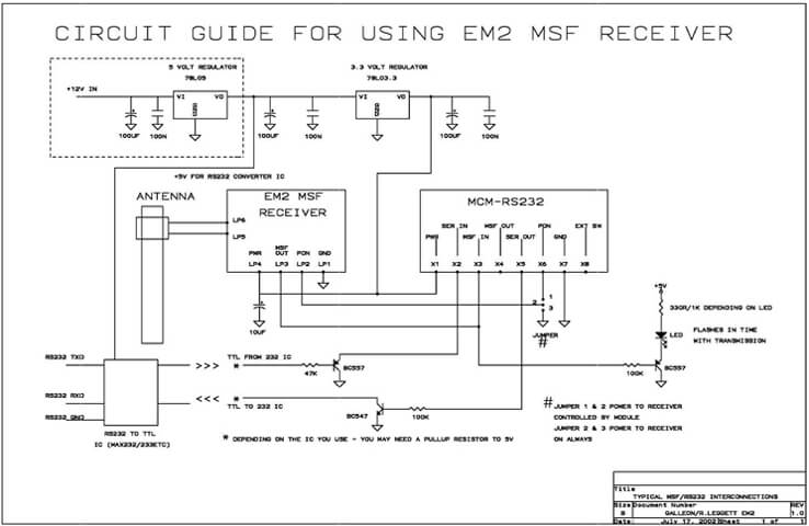
As Galleons modules are dedicated chips and include all necessary support electronics, tuned crystals and are a preassembled construction, it is incredibly simple to put together a simple MSF receiver, especially if you opt to use a dedicated power supply such as a 3v DC. A schematic of the basic wiring of the modules is included below. Note the optional use of an LED as in indicator that the device is working normally.

As the schematic demonstrates the modules are very simply wired together:
- The antenna is best laid horizontally as it is to be aligned with the direction of the MSF signal (when siting the device it is recommended to use a compass and map to locate the direction of the transmitter in Cumbria).
- The antenna is connected to the EM2 MSF module (LP6, LP5). The power supply connects to both the EM2 and the MCM-RS232 module (LP4, X1 3VOLTS, LP1,X7 ground).
- The EM2 and MCM modules are connected via the MSF out (LP3) and PON (LP2) on the EM2, to the MSF in (X3) and PON (X6) on the MCM module.
- The MCM - RS232 connects to a computer via a serial interface and the Serial in and out (X2 and X5)
- Note the location of capacitors and resistors. As mentioned earlier to overcome the problems associated with noise, some trial and error may be required in this area.
Software
There are several options when it comes to software to control the MSF receiver. Whilst there are multiple types of time synchronisation software available including freeware, Galleon Systems Time Sync version 3.2 is highly recommended. Time Sync has an easy to use interface and can synchronise to not only a radio receiver but also GPS and the Internet. Time Sync v 3.2 is also fully supported with a fully informative manual containing troubleshooting advice and a self explanatory interface. It also has many functions unavailable in smaller shareware synchronisation packages and will run on Linux and all versions of Windows (at least as far back as NT/2000). Galleon's software will automatically detect the device and send the time signal to the ntpd daemon (or service in Windows) which will run in the background. The program will also determine the MSF signal from the decoded pulses.
Troubleshooting and Accuracy
One of the main causes of problems with a simple radio receiver such as this one is noise. Even if the noise is filtered and smoothed out by the use of capacitors it only takes a small amount of noise, particularly when the signal is in a low state, to generate an error. If the daemon or service detects an error whilst trying to decode the time signal it aborts the current process and tries again. To reduce the interference it is important to keep the device away from metal objects, other electrical equipment (not always easy when its connected to a computer) and is kept still. It is also best to keep the device's antenna aligned at right angles as perfectly as possible to the location of the transmitter.
The biggest factor in defining accuracy of any radio clock is the distance from the transmitter, its propagation, the processing of the receiver, and the latency of the operating system. Because of all these factors a delay of up to 20 milliseconds can be expected and while this can be calibrated for in Time Sync v 3.2 accuracy up to 20 milliseconds is more than precise for most if not all time synchronisation needs.
Free Modules for Students
As part of Galleon Systems ongoing support for education we are pleased to be able to offer all the modules mentioned above absolutely free of charge to any student, university or college. Any lecturer or student interested in acquiring these modules please contact us on: 0121 608 7230 (UK) or +44 (121) 608 7230 (overseas) and Quote "EMC-FREE".